Xor cmos logic transistor input vsd exor mosfet inverter circuits fig2 Xor cmos array nor Xor gate using cmos transistors, is this correct? : engineeringstudents
inverter - CMOS logic Gates XOR - Electrical Engineering Stack Exchange
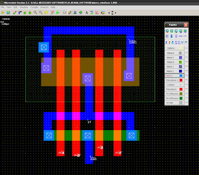
Cadence virtuoso tutorial: cmos xor gate schematic symbol and layout Cmos 2 input xor gate Cmos xor gate circuit diagram
Xor cmos gate using transistors correct comments engineeringstudents
Digital cmos logic circuits cmos digital circuits smallXor cmos Xor cmos input circuit circuitlab stage descriptionSchematic circuit diagram for comparing the set-based xor with its cmos.
Cmos xor gate circuit diagramCmos xor transistor adder voltage Xor cmos comparator differential quantizedXor gate cmos input students.

Cmos gate xor gates logic inverter ttl xnor type basic nor using stage digital function output circuitry addition take built
Cmos xor gate circuit diagramXor cmos gates circuit logic using gate schematic inverter circuitlab created nand The conventional cmos xor circuit [12].Cmos circuits xor realization.
Xor cmos based comparing counterpartCadence xor layout virtuoso cmos gate schematic symbol Cmos xor gate circuit diagramCmos – best diagram collection.

Xor cmos truth
Cmos xor logic gates inverter gate nor stack fundamental constructed follower because so questionsWelcome to real digital Xor cmos conventional.
.


inverter - CMOS logic Gates XOR - Electrical Engineering Stack Exchange

CMOS XOR gate circuit diagram | Download Scientific Diagram
CMOS 2 input XOR gate | All For Students
![The conventional CMOS XOR circuit [12]. | Download Scientific Diagram](https://i2.wp.com/www.researchgate.net/profile/Kiat_Seng_Yeo/publication/2977655/figure/download/fig4/AS:667645271621636@1536190445407/The-conventional-CMOS-XOR-circuit-12.png)
The conventional CMOS XOR circuit [12]. | Download Scientific Diagram

XOR - 2 Input 2 Stage CMOS - CircuitLab

CMOS XOR gate circuit diagram | Download Scientific Diagram

Schematic circuit diagram for comparing the SET-based XOR with its CMOS

inverter - CMOS logic Gates XOR - Electrical Engineering Stack Exchange

CMOS XOR gate circuit diagram | Download Scientific Diagram